
Defining Laser Cutting Accuracy
Laser cutting accuracy encompasses multiple dimensions: positioning accuracy (how precisely the laser follows intended paths), dimensional accuracy (how closely finished parts match design specifications), and repeatability (consistency across multiple parts). Understanding these distinctions enables realistic expectation setting and appropriate application of laser cutting for precision requirements. While laser cutting offers exceptional precision compared to many fabrication methods, absolute perfection remains elusive due to physical and process limitations.
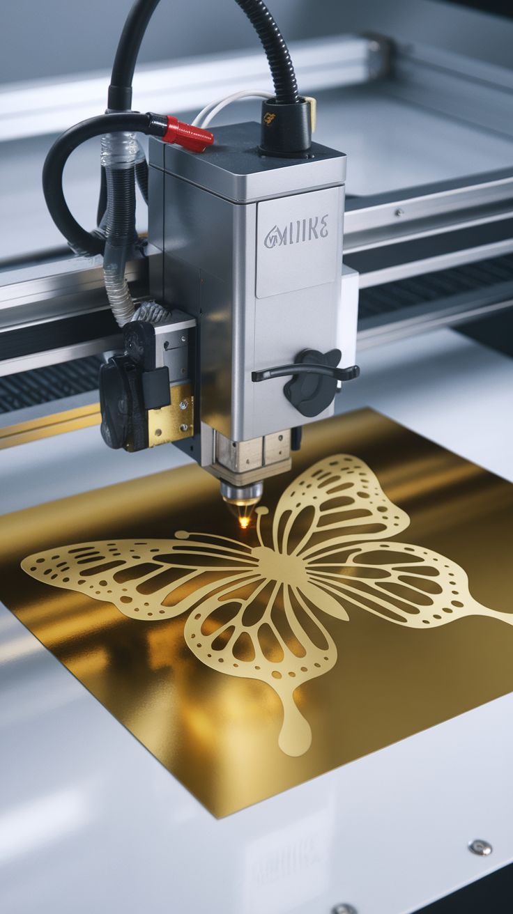
Positioning accuracy refers to the laser system's ability to move the cutting head to commanded locations. Quality CO2 laser systems achieve positioning accuracy of ±0.01mm (10 micrometers), with high-end industrial systems reaching ±0.005mm. This precision exceeds most mechanical cutting methods and enables intricate details impossible with conventional tooling. However, positioning accuracy represents only one component of final part accuracy—material behavior and process variables also influence dimensions.
Dimensional accuracy describes how closely cut parts match design specifications after processing. Typical laser cutting achieves dimensional tolerances of ±0.05mm to ±0.1mm for thin materials under stable conditions. This capability satisfies most commercial applications including precision assembly, interlocking parts, and detailed components. Tighter tolerances (±0.025mm) are achievable with optimized processes, material selection, and environmental control, but require specific expertise and equipment.
Factors Affecting Accuracy
Machine mechanical precision establishes baseline capability. Quality linear guides, drive systems, and structural rigidity maintain consistent positioning under dynamic cutting conditions. Wear in motion components, backlash in drive systems, or thermal expansion in machine structures degrade accuracy over time. Professional maintenance and calibration preserve accuracy; neglected equipment gradually loses precision. Regular verification against known standards identifies accuracy drift before it affects production.
Beam characteristics influence cut precision. Laser beam diameter at focus (spot size) typically ranges 0.1-0.3mm for CO2 lasers, determining minimum feature size and kerf width. Beam quality (mode stability) affects consistency across the cutting field—poor beam quality produces varying cut widths and depths. Lens condition critically affects focus stability; dirty or damaged lenses scatter light, enlarging effective spot size and reducing precision. Beam alignment ensures perpendicular cutting and consistent kerf geometry.
Material behavior introduces variables beyond machine control. Thermal expansion during heating causes material movement affecting cut location. Material non-uniformity (density variations, internal stresses) produces inconsistent cutting responses. Thickness variations across sheets affect focus position and cut penetration. These material factors often dominate final accuracy, explaining why identical machine settings produce varying results on different material batches.
| Factor | Impact on Accuracy | Mitigation Strategies |
|---|---|---|
| Machine calibration | Baseline positioning error | Regular maintenance, laser alignment |
| Lens condition | Spot size variation, focus drift | Cleaning schedules, replacement protocols |
| Material stability | Thermal movement, warping | Fixturing, pre-stress relief, material selection |
| Assist gas pressure | Cut geometry variation | Regulated pressure, consistent flow |
| Cutting speed | Kerf width variation | Optimized parameters, speed control |
| Environmental temp | Machine thermal expansion | Climate control, warmup periods |
| Material thickness | Focus position variation | Auto-focus systems, thickness verification |
Kerf Width and Dimensional Compensation
Kerf width—the material removed by the laser beam—typically measures 0.1-0.3mm depending on laser type, power, material, and speed. This width means cut parts are smaller than design dimensions by half the kerf width per side, while holes are larger by the same amount. For precision assemblies, designers must compensate for kerf width in specifications or providers must adjust cutting paths. Standard kerf compensation assumes nominal beam width, but actual kerf varies with material and parameters.
Kerf width variation occurs due to material properties and cutting conditions. Dense materials cut with narrower kerfs than soft materials at identical settings. Cutting speed affects kerf width—slower speeds widen kerf due to increased heat input. Assist gas pressure influences kerf geometry and width. These variations mean that kerf compensation optimized for one material may prove slightly off for another, affecting precision assemblies.
Taper in cut edges creates dimensional variation through material thickness. Laser beams converge to focal points then diverge, creating slight taper in thick materials—typically 0.5-2 degrees depending on thickness and lens focal length. This taper means top and bottom dimensions differ slightly, significant for precision fits in thick materials. Strategies to minimize taper include using longer focal length lenses, multiple-pass cutting, or design compensation for the intended assembly side.
Repeatability and Consistency
Repeatability—the variation between supposedly identical parts—often matters more than absolute accuracy for production applications. Quality laser systems achieve repeatability of ±0.01mm under stable conditions, meaning consecutive parts match closely even if absolute dimensions vary slightly. This consistency enables reliable assembly without individual fitting and maintains quality across production runs. Repeatability depends on machine stability, material consistency, and process control.
Batch-to-batch variation presents greater challenges than within-batch consistency. Different material lots may have slightly different thicknesses, densities, or compositions affecting cutting behavior. Environmental changes (temperature, humidity) alter machine and material behavior between production runs. Maintaining consistency across batches requires material qualification, environmental control, and process monitoring. For critical applications, batch-specific parameter adjustment ensures consistent results.
Tool path optimization affects consistency. Continuous cutting paths maintain stable thermal conditions and motion dynamics, producing uniform edges. Interrupted cutting, sharp direction changes, or complex geometry create varying thermal loads and acceleration forces affecting consistency. Design for continuous cutting where possible, and accept that complex geometries may show slight variation in detailed areas.
Accuracy Across Material Types
Acrylic cutting achieves excellent accuracy due to material consistency and clean vaporization. Cast acrylic offers superior dimensional stability compared to extruded, with more uniform composition producing predictable cutting behavior. Typical acrylic cutting maintains ±0.05mm tolerance in 3-6mm thickness, suitable for precision assemblies, interlocking parts, and detailed models. Edge quality supports accurate measurement—clean, square edges enable precise dimensional verification.
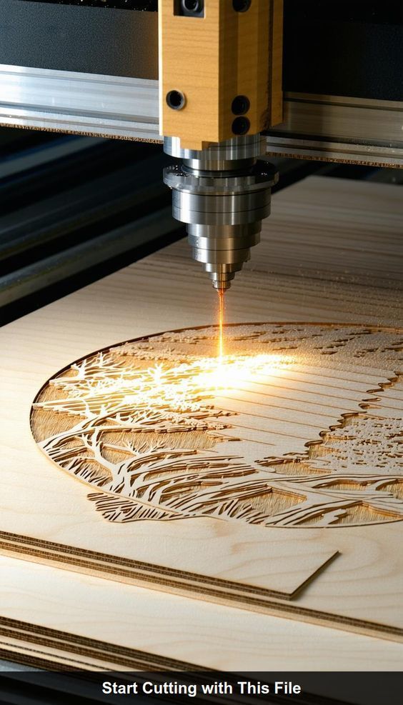
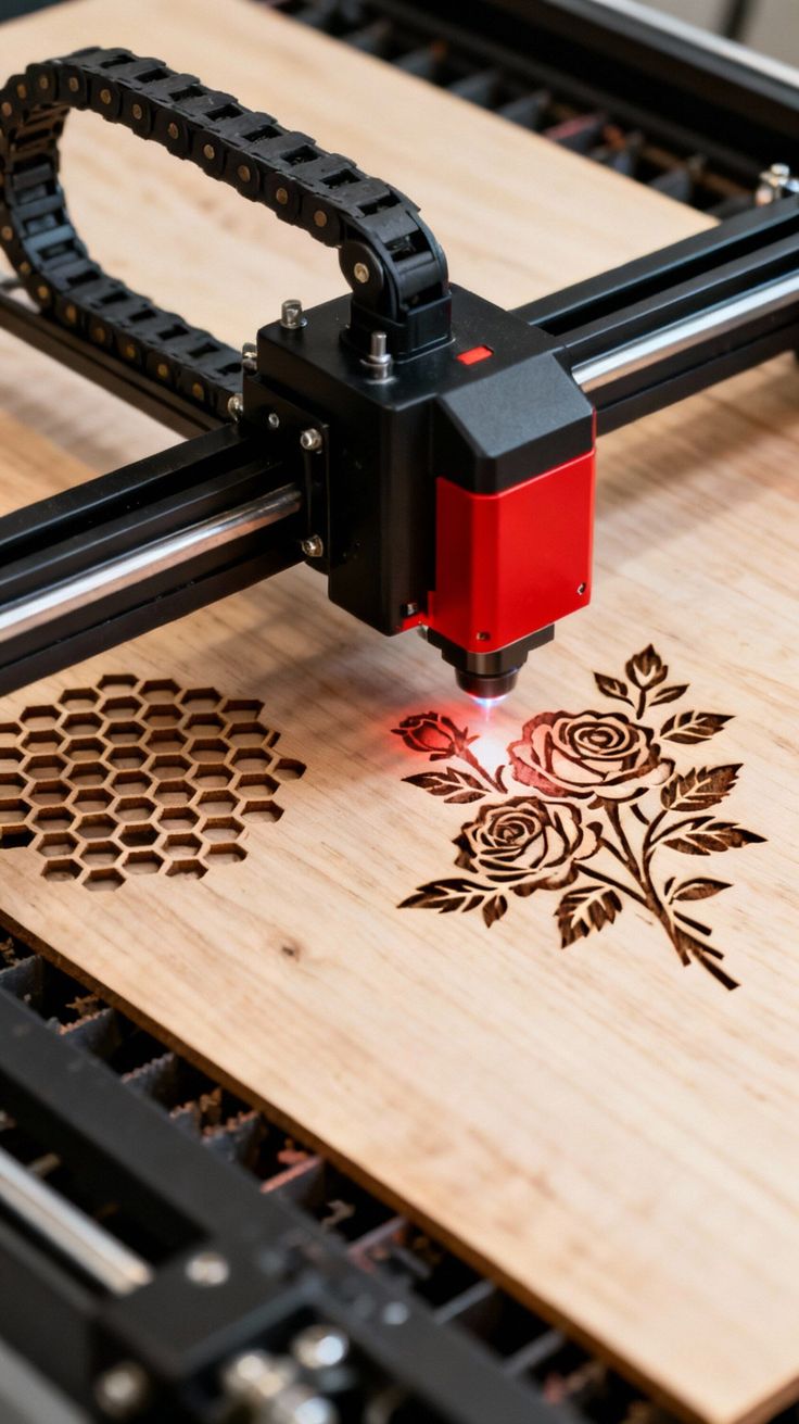
Wood and plywood accuracy varies with material characteristics. Natural wood density variations, grain patterns, and moisture content create cutting rate variations affecting dimensions. Plywood adds glue line inconsistencies and core voids. Tolerances of ±0.1-0.2mm are realistic for wood products, adequate for most furniture, decorative, and structural applications but insufficient for precision mechanical assemblies. Material selection (quality plywood, stable hardwoods) and conditioning improve consistency.
Metal cutting accuracy depends on type and thickness. Thin sheet metals (under 3mm) cut with high precision on fiber lasers, achieving ±0.05mm tolerances suitable for precision components. Thicker metals show increased heat-affected zones and dross formation affecting edge quality and consistency. Stainless steel cuts more precisely than mild steel due to cleaner edge formation. Aluminum's high thermal conductivity challenges consistency, requiring optimized parameters for stable results.
Textiles and leather offer good accuracy for flexible materials, typically ±0.1-0.2mm, though material stretch and compression during handling introduce variability. Laser sealing of edges prevents fraying but slightly affects dimensions through melting. For applications requiring precise pattern matching or assembly, allow tolerance for material behavior and test fit before production commitment.
Measuring and Verifying Accuracy
Metrology requirements for laser-cut parts depend on application criticality. Standard calipers and micrometers suffice for most commercial tolerance verification. Critical applications require coordinate measuring machines (CMM) or optical comparators for comprehensive dimensional verification. Edge quality assessment requires visual inspection or microscopy to evaluate squareness, striation patterns, and surface finish.
Statistical process control monitors accuracy trends over time. Measuring sample parts from production runs tracks accuracy drift and identifies when maintenance or parameter adjustment is needed. Control charts plotting dimensions against tolerance limits visualize process stability. This proactive approach prevents out-of-tolerance parts from reaching customers and identifies root causes of variation.
First article inspection validates setup accuracy before production. Cutting single parts, measuring comprehensively, and comparing to specifications identifies setup errors, file problems, or parameter issues before material waste. For precision applications, first article approval gates production release. This discipline prevents expensive scrap and ensures customer specifications are understood and achievable.
Designing for Laser Cutting Accuracy
Tolerance specification should match application requirements without over-constraining. Unnecessarily tight tolerances increase costs through slower cutting, increased inspection, and higher rejection rates. Specify tight tolerances only where functionally necessary—assembly interfaces, mounting features, or mating surfaces. Non-critical aesthetic features can have looser tolerances reducing cost without impacting function.
Design features accommodating expected tolerances ensure assembly success. Clearance holes for fasteners should exceed nominal sizes to accommodate position variation. Slot widths for press-fit assembly should include tolerance for material thickness variation and kerf width uncertainty. Tab-and-slot designs work best with slight clearance rather than interference fits requiring precise tolerance control.
Reference datums establish consistent measurement baselines. Designate primary surfaces or edges as datums for dimensioning, ensuring consistent measurement approaches between provider and customer. Avoid chaining dimensions from feature to feature, accumulating tolerance variation. Direct dimensioning from datums to critical features minimizes tolerance stack-up.
Luna Graphics maintains rigorous accuracy standards through equipment maintenance, process control, and quality verification. Our laser systems undergo regular calibration, our operators are trained in precision techniques, and our quality processes verify accuracy before parts reach customers. We consult with clients on appropriate tolerance specifications for applications, ensuring that precision capabilities align with functional requirements without driving unnecessary costs. Contact us to discuss your accuracy requirements and discover how professional laser cutting delivers the precision your projects demand.
Written by Ian Love
Marketing Director
Professional contributor at Luna Graphics specializing in printing and branding solutions.