
The Precision of Complex CNC Cutting
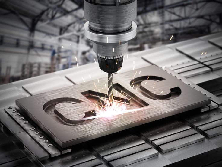
CNC cutting technology transcends simple profile cutting to enable intricate designs previously achievable only through painstaking handwork or expensive specialized tooling. Fine detail, complex geometries, and sophisticated patterns execute with consistency and precision, opening design possibilities across industries from luxury goods to architectural features. Understanding CNC capabilities for complex work enables designers to leverage technology effectively.
Complexity in CNC cutting manifests in multiple dimensions: fine features (small holes, thin webs, intricate profiles); 3D surfaces (contours, reliefs, sculptural forms); tight tolerances (precision fitting, interlocking parts); and pattern density (perforated screens, lace-like cutouts). Each complexity type presents specific challenges and requires appropriate equipment, tooling, and parameters.
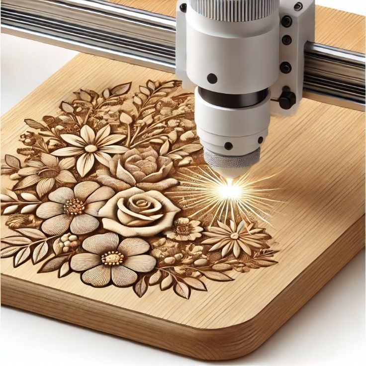
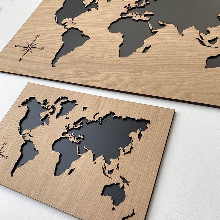
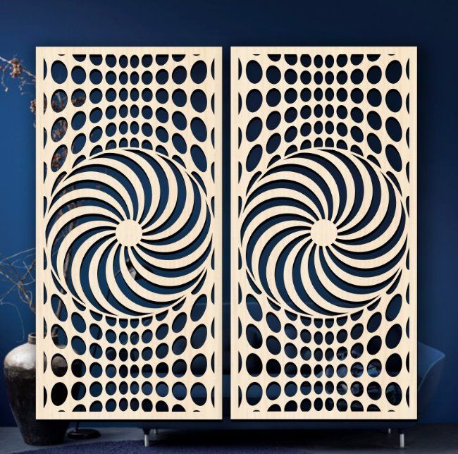
The Kenyan design community increasingly utilizes complex CNC cutting for differentiated products and installations. Architectural screens with intricate patterns, furniture with detailed inlay, signage with fine lettering, and decorative elements with sculptural depth demonstrate technology capabilities. Realizing these applications requires understanding both possibilities and constraints.
Fine Detail and Small Feature Machining
Minimum Feature Sizes: Practical minimum feature sizes depend on tool diameter and material characteristics. Standard end mills range 1-12mm diameter; micro-tooling extends to 0.2mm for specialized applications. However, tool rigidity decreases dramatically with diameter—small tools deflect under cutting forces, limiting practical depth and material hardness.
General guidelines for minimum features:
- Minimum slot width: 1.0-1.5x tool diameter (chip evacuation requirement)
- Minimum inside corner radius: tool radius (cannot cut sharper than tool)
- Thin webs/ribs: minimum 1.5-2mm for rigidity during cutting
- Small holes: down to 1mm in soft materials with appropriate drills
Tooling for Fine Work: Micro-end mills (1-3mm diameter) with high flute density enable fine detail. High-speed spindles (24,000+ RPM) maintain appropriate surface speed with small tools. Tool material critical—solid carbide provides rigidity and edge retention essential for small features. Tool runout (rotation eccentricity) must be minimized—high-precision collets and balanced tooling prevent feature distortion.
Material Considerations: Soft materials (foam, soft woods) allow finer features than dense materials (hardwoods, metals). Material grain or structure affects minimum features—MDF machines finer details than solid wood; acrylic allows precise features if heat managed. Material stability during cutting prevents small feature destruction—adequate workholding essential.
| Material | Minimum Practical Feature | Best Detail Applications | Special Considerations |
|---|---|---|---|
| MDF | 1.5mm slots, 2mm webs | Intricate fretwork, patterns | Clean, uniform cutting |
| Birch Plywood | 2.0mm slots, 3mm webs | Decorative panels, screens | Face veneer chip-out risk |
| Acrylic (thin) | 1.0mm slots, 1.5mm webs | Fine lettering, jewelry | Heat management critical |
| Acrylic (thick) | 2.0mm slots, 3mm webs | Dimensional signage | Slower speeds prevent melting |
| Aluminum (sheet) | 1.5mm slots, 2.5mm webs | Precision components | Sharp tools, conservative feeds |
| Foam (high density) | 1.0mm slots, 1.5mm webs | Prototypes, models | Very fast cutting possible |
3D Contouring and Relief Machining
3D Capability Requirements: True 3D cutting requires multi-axis machines. Three-axis machines (X, Y, Z) handle 2.5D work—pockets, profiles, and stepped geometries. Four-axis adds rotation (typically A-axis around X), enabling cylindrical work and indexed positioning. Five-axis simultaneous movement creates complex sculptural forms with undercuts and compound curves.
Surface Finish Quality: 3D surface quality depends on step-over (distance between tool passes) and tool geometry. Smaller step-overs create smoother surfaces but increase machining time exponentially. Ball-end tools create smooth contours; flat-end tools leave faceted surfaces requiring finishing. Tool diameter affects minimum radius capability—small ball mills (1-3mm) create fine detail with acceptable surface finish.
CAM Strategies: 3D toolpath generation requires sophisticated CAM software. Strategies include:
- Raster (Z-level): Horizontal passes at varying depths, efficient for steep walls
- Parallel (planar): Parallel passes across surface, good for shallow areas
- Radial: Circular pattern from center, effective for bowl-like forms
- Spiral: Continuous spiral path, excellent surface finish
- Pencil milling: Cleanup along intersection lines and tight corners
Design for 3D Machining: Undercuts require 4th or 5th axis capability; 3-axis machines cannot cut surfaces parallel to spindle axis. Draft angles facilitate machining and mold release if applicable. Minimum corner radii determined by tool size—internal sharp corners impossible without secondary operations.
Complex Pattern and Perforation Work
Pattern Density: Dense perforation patterns (high open area percentage) challenge material stability during cutting. Strategic sequencing—cutting from center outward, leaving connecting tabs until final passes—maintains sheet integrity. Vacuum table hold-down critical; inadequate holding causes material movement destroying precision.
Web Design: Thin webs between cutouts must balance aesthetic openness against structural integrity. Minimum web thickness depends on material and sheet size—larger sheets require thicker webs to prevent distortion. Finite element analysis or empirical testing validates web design for structural requirements.
Pattern Types: CNC cutting creates diverse pattern categories:
- Geometric perforations: Regular holes, slots, hexagons—efficiently programmed and cut
- Organic patterns: Curved, nature-inspired forms requiring smooth toolpaths
- Bitmap conversion: Images converted to halftone patterns through varying hole sizes/density
- Variable perforation: Pattern density varying across surface for acoustic or visual gradient effects
- Lattice structures: Interconnected struts creating 3D open structures
Multi-Level and Layered Designs
2.5D Layering: Designs incorporating multiple depth levels create visual interest and functional features without full 3D complexity. Pocketing operations at varying depths create relief effects; through-cutting combined with partial-depth cutting enables multi-level assemblies.
Laminated Constructions: Complex 3D forms built from multiple 2D-cut layers stacked and bonded. This approach offers advantages: each layer machines efficiently as 2D profile; internal features accessible between layers; material efficiency through nesting; and color/material variation between layers. Applications include topographic models, sculptural forms, and intricate decorative elements.
Inlay and Marquetry: Precision cutting enables intricate inlay work—contrasting materials cut to interlock precisely. Tight tolerances (0.1-0.2mm) ensure gap-free assembly. Multiple materials (woods, plastics, metals) combine for decorative effect. Vacuum pressing or adhesive bonding secures inlay elements.
Technical Optimization for Complex Work
Machine Calibration: Complex work demands maximum machine precision. Backlash compensation, squareness verification, and spindle runout minimization essential. Temperature stability prevents dimensional drift during long machining operations.
Workholding Innovation: Complex parts often require creative fixturing—vacuum fixtures conforming to part geometry, adhesive mounting on sacrificial substrates, or mechanical fixtures with quick-release mechanisms. Fixture design significantly affects achievable complexity.
Toolpath Optimization: Efficient programming reduces machining time and improves quality. Adaptive clearing strategies optimize material removal; finishing strategies minimize tool marks; and entry/exit moves prevent witness marks on visible surfaces. Simulation verifies toolpaths before cutting, preventing collisions and identifying optimization opportunities.
Quality Verification: Complex parts require thorough inspection—CMM measurement for precision features, visual inspection for surface quality, and fit checking for assembly components. First-article approval particularly critical for complex production runs.
Luna Graphics specializes in complex CNC cutting for demanding design applications. Our multi-axis capabilities, precision tooling inventory, and programming expertise transform intricate designs into physical reality. From architectural screens to sculptural furniture, we deliver complex geometry with precision and consistency. Contact our design engineering team to discuss your complex cutting requirements.
Written by Ian Love
Marketing Director
Professional contributor at Luna Graphics specializing in printing and branding solutions.