
Defining Thickness in CNC Cutting
Thickness capability in CNC cutting represents a complex interaction between machine specifications, tooling characteristics, material properties, and quality requirements. Unlike simple maximum depth specifications, practical thickness limits vary significantly based on these factors. Understanding thickness constraints enables effective design and material selection optimizing manufacturing outcomes.
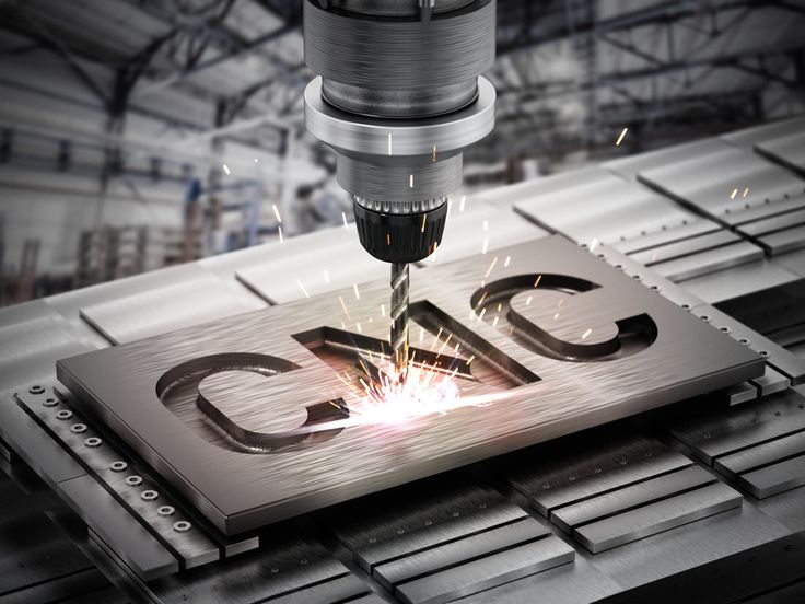
CNC cutting differs from through-cutting processes like sawing or shearing—rotating tools remove material progressively, with each pass limited by tool geometry, machine power, and chip evacuation. Thick material processing requires strategies balancing efficiency against quality, often utilizing multiple passes rather than single deep cuts.
The Kenyan CNC cutting market primarily processes sheet goods under 50mm thickness, with architectural and industrial applications occasionally requiring thicker material handling. Standard machine configurations optimize for 3-25mm materials, with specialized capabilities extending range for specific needs.
Machine Factors Affecting Thickness Capability
Z-Axis Travel: Physical machine dimension determining maximum material thickness plus tool length. Standard CNC routers offer 150-300mm Z-axis travel; industrial machines may provide 500mm+. However, available travel differs from practical cutting depth—tool extension, workholding height, and clearance requirements reduce effective cutting capacity.
Spindle Power and Torque: Cutting thick material requires power to maintain speed under load. Spindle power (measured in horsepower or kilowatts) and torque characteristics determine material removal capability. Heavy cutting in dense materials demands robust spindles (5HP+) with appropriate torque curves maintaining speed under load.
Machine Rigidity: Cutting forces increase with material thickness and density. Machine structure must resist deflection under these forces—light-duty machines flex during heavy cutting, causing vibration, poor surface finish, and potential damage. Gantry design, frame construction, and component quality determine rigidity.
Tool Length and Stability: Cutting deep requires long tool extension from collet, reducing stability. Tool deflection increases with extension length, affecting accuracy and surface finish. Specialized long-reach tools or extended collets may enable deeper cutting but with compromised performance.
| Machine Class | Typical Z-Travel | Practical Cutting Depth | Best Material Thickness | Applications |
|---|---|---|---|---|
| Hobby/Desktop | 50-100mm | Up to 25mm | 3-12mm | Craft, prototyping, signage |
| Light Industrial | 150-200mm | Up to 50mm | 3-25mm | Signage, furniture, general |
| Industrial Router | 200-300mm | Up to 75mm | 6-50mm | Architectural, industrial |
| Heavy Industrial | 300-500mm | Up to 150mm | 12-100mm | Molds, large components |
| CNC Mill | Variable | Unlimited (in theory) | Metal plate, heavy stock | Precision metalwork |
Material-Specific Thickness Considerations
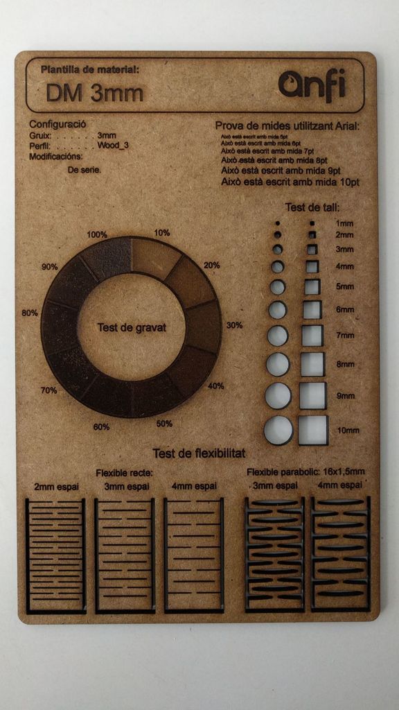
Wood and MDF: Soft materials machine easily even in substantial thickness. Standard industrial routers handle 50mm MDF or solid wood effectively with appropriate tooling and multi-pass strategies. Thicker material (75-100mm) possible with specialized equipment or slower processing. Primary constraints become machine Z-travel and tool length rather than cutting power.
Plastics: Thermal sensitivity limits practical thickness in plastics. Deep cutting generates heat potentially melting material or degrading edge quality. Acrylic over 25mm requires careful parameter management—slow speeds, excellent chip evacuation, and possible coolant use. Engineering plastics generally machine thicker sections more readily than acrylic due to higher thermal resistance.
Aluminum: Sheet aluminum (under 6mm) cuts efficiently on quality routers. Plate aluminum (6-25mm) requires robust equipment and appropriate parameters—slower speeds, coolant, and multi-pass cutting. Thicker aluminum plate (25mm+) generally requires CNC mill capabilities rather than routing equipment.
Composites: Material construction affects thickness capability. Solid composites machine similarly to constituent materials. Sandwich panels (honeycomb, foam core) require careful parameter management preventing core crushing or face delamination. Thick carbon fiber machining generates significant heat and abrasion requiring specialized approaches.
Multi-Pass Cutting Strategies
Thick material processing typically utilizes multi-pass cutting—successive depth increments achieving full penetration. This approach offers advantages over single deep cuts:
Roughing and Finishing: Initial passes (roughing) remove bulk material aggressively; final pass (finishing) achieves dimensional accuracy and surface quality at full depth. Roughing may use larger tools and faster feeds; finishing employs appropriate tools for final dimensions.
Step-Down Calculations: Optimal depth per pass varies by material and tool diameter. General guidelines:
- Soft woods/MDF: 1-1.5x tool diameter per pass
- Hardwoods: 0.5-1x tool diameter
- Plastics: 0.5-1x tool diameter (thermal management critical)
- Aluminum: 0.25-0.5x tool diameter (conservative for heat/chip management)
Tool Path Optimization: Depth-first cutting (completing one area to full depth before moving) versus level-first (cutting entire profile at each depth increment) offer different advantages. Depth-first reduces tool retraction but may compromise chip evacuation in deep pockets. CAM software optimizes based on geometry and material.
Designing for Thickness Constraints
Lamination Approaches: Thick components fabricated by laminating thinner CNC-cut layers rather than cutting from solid stock. This approach offers advantages: thinner material machines faster and more accurately; internal features accessible between layers; material efficiency through nesting; and reduced internal stress. Applications include dimensional lettering, sculptural forms, and thick structural elements.
Profile Optimization: Designs requiring thick material may optimize through hollow construction or ribbing rather than solid sections. This reduces material cost, machining time, and weight while maintaining structural performance. CNC cutting creates interlocking components or pocketed designs achieving apparent thickness efficiently.
Material Selection: Thickness requirements influence material choice. ACP provides rigidity at 3-6mm equivalent to much thicker solid aluminum. High-density foam creates volumetric forms without material weight. Structural requirements may be met through engineering rather than material bulk.
Assembly Strategies: Thick components built up from thinner CNC-cut parts joined mechanically or adhesively. This approach enables features impossible in single-piece cutting—internal cavities, varying materials, or complex 3D geometry. Design for assembly considerations include joint design, alignment features, and fastening methods.
Quality Considerations in Thick Material Cutting
Edge Quality: Thick material edges show more pronounced tooling marks, potential burning (in materials prone), and reduced perpendicularity compared to thin sections. Finishing passes at full depth with sharp tooling improve quality; post-machining sanding or edge treatments may be necessary for visible applications.
Dimensional Accuracy: Tool deflection increases with cutting depth, potentially affecting dimensional precision in thick materials. Finishing allowances and spring-pass techniques (light cleanup pass at full depth) address these effects. Rigid tooling and conservative parameters minimize deviation.
Internal Stress: Thick material cutting releases internal stresses causing distortion. This particularly affects materials with residual manufacturing stress (cast acrylic, extruded metals). Stress-relieving before cutting or design accommodations for movement may be necessary for precision applications.
Luna Graphics advises clients on thickness optimization for their specific applications, balancing material requirements against manufacturing efficiency. Our equipment handles substantial thickness across material categories, with engineering support for design strategies maximizing material capabilities. Contact our technical team to discuss your thickness requirements and discover optimal approaches for your projects.
Written by Ian Love
Marketing Director
Professional contributor at Luna Graphics specializing in printing and branding solutions.